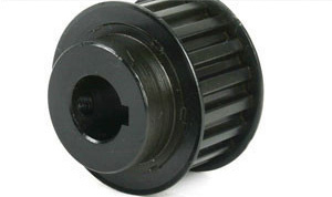
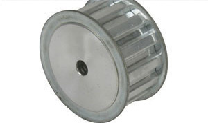
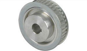
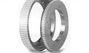
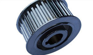
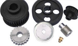
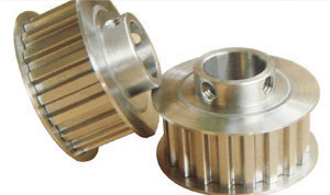
Synchronous pulley
-
Imperial Synchronous pulley
Imperial Synchronous pulley tooth shape classification: MXL type, XL type, L type, H type, XH type, XXH type
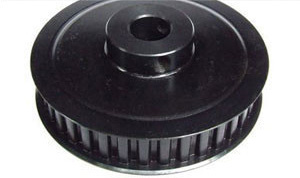
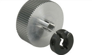
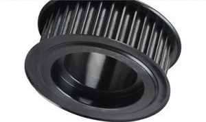
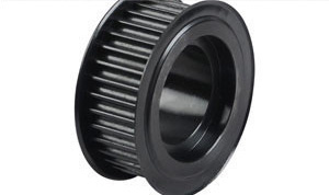
British Synchronous pulley Raw materials: generally made of steel, aluminum alloy, cast iron, brass, and other materials. The inner hole has round hole, D-shaped hole, conical hole and other forms.
British Synchronous pulley surface treatment: natural oxidation, blackening, zinc plating, color zinc plating, high frequency quenching and other treatment. Accuracy level depends on customer requirements.
1, our factory production of the British ladder Synchronous pulley for the domestic equipment of the British trapezoidal Synchronous belt supporting, but also can replace the imported British trapezoidal Synchronous pulley use.
2, user customized British type Synchronous pulley, please provide pulley drawing (the drawing can not draw the tooth shape size of the pulley), our factory can also draw pulley drawing according to the specifications provided by the user, pulley inner hole, keyway, width and other dimensions for the user.
3, our factory inch ladder type Synchronous pulley can be processed according to user needs, and our factory can also develop drawings for users.
Presentation method Code Material Surface treatment 
LYA Aluminum alloy Natural anodizing LYZ Hard oxidation LYH Do not process LYY 45# steel Blackening treatment LYD Galvanizing LYM Do not process 
Standard keyway size table (dH7: indicates inner hole size; bJS9: indicates the keyway width; t tolerance: keyway depth Model dH7 bJS9 t tolerance Model dH7 bJS9 t tolerance Model dH7 bJS9 t tolerance N8 8 +0.015
03 ±0.0125 1.4 +0.1
0N23 23 +0.021
08 ±0.018 3.3 +0.2
0N38 38 +0.025
010 ±0.018 3.3 +0.2
0N10 10 N24 24 N39 39 12 ±0.0215 NK10 10 +0.018
04 ±0.015 1.8 N25 25 N40 40 N11 11 N26 26 N41 41 N12 12 2.3 N27 27 N42 42 N13 13 N28 28 N43 43 N14 14 5 N29 29 N44 44 N15 15 N30 30 N45 45 14 3.8 N16 16 N31 31 N46 46 N17 17 N32 32 +0.025
010 N47 47 N18 18 6 2.8 N33 33 N48 48 N19 19 +0.021
0N34 34 N49 49 N20 20 N35 35 N50 50 N21 21 N36 35 N22 22 N37 37 Note: When the shaft hole is 10, the keyway width is 4.0MM, and the keyway depth is 1.8MM, the shaft hole is represented by NK10 Model MXL XXL XL L H XH XXH Width bw 0.84±0.05 1.14±0.05 1.32±0.05 3.05±0.10 4.19±0.13 7.90±0.15 12.17±0.18 Depth hg 0.69 0 0.84 0 1.65 0 2.67 0 3.05 0 7.14 0 10.31 0 0.05 0.05 0.08 0.10 0.13 0.13 0.13 Slot half Angle Φ+1.5° 20 25 25 20 20 20 20 Root radius rb 0.35 0.35 0.41 1.19 1.60 1.98 3.96 Tip radius rt 0.13 + 0.05 0.30 + 0.05 0.64 + 0.05 1.17 + 0.13 1.60 + 0.13 2.39 + 0.13 3.18 + 0.13 0 0 0 0 0 0 0 Double pitch 2β 0.508 0.508 0.508 0.762 1.372 2.794 3.048 -
Metric T-Synchronous pulley
Metric T-Synchronous pulley tooth type classification: T2.5, T5, T10, T20, AT5, AT10
Metric T-synchronous pulley Raw materials: generally made of steel, aluminum alloy, cast iron, brass, and other materials. The inner hole has round hole, D-shaped hole, conical hole and other forms.
Metric T type Synchronous pulley surface treatment: natural oxidation, blackening, zinc plating, color zinc plating, high-frequency quenching and other treatment. Accuracy level depends on customer requirements.
1, our factory produces metric T-synchronous pulley not only for the domestic equipment of the metric T-synchronous belt supporting, but also can replace the imported T-synchronous pulley use.
2, user customized metric T-type Synchronous pulley, please provide pulley drawings (the drawing can not draw the tooth shape size of the pulley), our factory can also draw pulley drawings according to the specifications provided by the user, the inner hole of the pulley, the keyway, the width and other dimensions for the user.
3, our factory metric T-type Synchronous pulley can be processed according to user needs, and our factory can also develop drawings for users.
Presentation method Code Material Surface treatment 
LYA Aluminum alloy Natural anodizing LYZ Hard oxidation LYH Do not process LYY 45# steel Blackening treatment LYD Galvanizing LYM Do not process 
Standard keyway size table (dH7: indicates inner hole size; bJS9: indicates the keyway width; t tolerance: keyway depth Model dH7 bJS9 t tolerance Model dH7 bJS9 t tolerance Model dH7 bJS9 t tolerance N8 8 +0.015
03 ±0.0125 1.4 +0.1
0N23 23 +0.021
08 ±0.018 3.3 +0.2
0N38 38 +0.025
010 ±0.018 3.3 +0.2
0N10 10 N24 24 N39 39 12 ±0.0215 NK10 10 +0.018
04 ±0.015 1.8 N25 25 N40 40 N11 11 N26 26 N41 41 N12 12 2.3 N27 27 N42 42 N13 13 N28 28 N43 43 N14 14 5 N29 29 N44 44 N15 15 N30 30 N45 45 14 3.8 N16 16 N31 31 N46 46 N17 17 N32 32 +0.025
010 N47 47 N18 18 6 2.8 N33 33 N48 48 N19 19 +0.021
0N34 34 N49 49 N20 20 N35 35 N50 50 N21 21 N36 35 N22 22 N37 37 Note: when the shaft hole is 10, the keyway width is 4.0MM, and the keyway depth is 1.8MM, the shaft hole is indicated by NK10 Model Pitch Pb Tooth profile Angle 2y° Top width br Tooth height hg Root radius rb Tip radius rt T2.5 2.50 50 1.83 1.00 0.20 0.30 T5 5.00 3.32 1.95 0.40 0.60 T10 10.00 6.57 3.40 0.60 0.80 T20 20.00 12.6 6.00 0.80 1.20 Model Pitch Pb Tooth profile Angle 2y° Slot width S Tooth height hg Root radius rr Tip radius ra AT3 3.00 50 1.50 1.00 0.20 0.30 AT5 5.00 2.70 1.10 0.40 0.70 AT10 10.00 5.40 2.35 0.50 1.20 AT20 20.00 10.00 5.00 1.75 2.50 -
HTD Circular Tooth Synchronous pulley
HTD circular tooth Synchronous pulley Profile classification: HTD2M type, HTD3M type, HTD5M type, HTD8M type, HTD14M type, HTD20M type
HTD circular tooth Synchronous pulley Raw materials: generally made of steel, aluminum alloy, cast iron, brass, and other materials. The inner hole has round hole, D-shaped hole, conical hole and other forms.
HTD circular tooth Synchronous pulley surface treatment: natural oxidation, blackening, zinc plating, color zinc plating, high frequency quenching and other treatment. Accuracy level depends on customer requirements.
1, our factory production of HTD circular tooth Synchronous pulley for the domestic equipment of HTD circular tooth Synchronous belt supporting, but also can replace the imported HTD circular tooth Synchronous pulley use.
2, user customized HTD circular tooth Synchronous pulley, please provide pulley drawing (the drawing can not draw the tooth shape size of the pulley), our factory can also draw pulley drawing according to the specifications provided by the user, the inner hole of the pulley, the keyway, the width and other dimensions for the user.
3, our factory HTD circular tooth Synchronous pulley can be processed according to user needs, and our factory can also develop drawings for users.
Presentation method Code Material Surface treatment 
LYA Aluminum alloy Natural anodizing LYZ Hard oxidation LYH Do not process LYY 45# steel Blackening treatment LYD Galvanizing LYM Do not process 
Standard keyway size table (dH7: indicates the inner hole size; bJS9: indicates the keyway width; t tolerance: indicates the depth of the keyway Model dH7 bJS9 t tolerance Model dH7 bJS9 t tolerance Model dH7 bJS9 t tolerance N8 8 +0.015
03 ±0.0125 1.4 +0.1
0N23 23 +0.021
08 ±0.018 3.3 +0.2
0N38 38 +0.025
010 ±0.018 3.3 +0.2
0N10 10 N24 24 N39 39 12 ±0.0215 NK10 10 +0.018
04 ±0.015 1.8 N25 25 N40 40 N11 11 N26 26 N41 41 N12 12 2.3 N27 27 N42 42 N13 13 N28 28 N43 43 N14 14 5 N29 29 N44 44 N15 15 N30 30 N45 45 14 3.8 N16 16 N31 31 N46 46 N17 17 N32 32 +0.025
010 N47 47 N18 18 6 2.8 N33 33 N48 48 N19 19 +0.021
0N34 34 N49 49 N20 20 N35 35 N50 50 N21 21 N36 35 N22 22 N37 37 Note: When the shaft hole is 10, the keyway width is 4.0MM, and the keyway depth is 1.8MM, the shaft hole is represented by NK10 Trough type Pitch pb Depth hg Slot radius R Tip circle half Angle r1 Slot width s Double pitch 2δ Tooth profile Angle 3M 3 1.28 0.91 0.26~0.35 1.90 0.762 ≈14° 5M 5 2.16 1.56 0.48~0.52 3.25 1.144 ≈14° 8M 8 3.54 2.57 0.78~0.84 5.35 1.372 ≈14° 14M 14 6.20 4.65 1.36~1.50 9.80 2.794 ≈14° 20M 20 8.60 6.84 1.95~2.25 14.80
4.320 ≈14° -
STS/STD Synchronous pulley
STS/STD tooth Synchronous pulley also known as semi-circular tooth Synchronous pulley.
STS/STD Synchronous pulley Category: S2M, S3M, S4.5M, S5M, S8M, S14M
STS/STD Synchronous pulley Raw materials: Generally made of steel, aluminum alloy, cast iron, brass, etc. The inner hole has round hole, D-shaped hole, conical hole and other forms.
STS/STD Synchronous pulley surface treatment: Natural oxidation, blackening, zinc plating, color zinc plating, high frequency quenching and other treatment. Accuracy level depends on customer requirements.
1. The STS/STD Synchronous pulley produced by our factory is not only for the STS/STD Synchronous belt of domestic equipment, but also can replace the imported STS/STD Synchronous pulley.2, user customized STS/STD Synchronous pulley, please provide pulley drawing (it is not necessary to draw the tooth shape size of the pulley in the drawing), our factory can also draw pulley drawing according to the specifications provided by the user, the inner hole of the pulley, the keyway, the width and other dimensions for the user.
3, our factory STS/STD Synchronous pulley can be processed according to user needs, and our factory can also develop drawings for users.
Presentation method Code Material Surface treatment 
LYA Aluminum alloy Natural anodizing LYZ Hard oxidation LYH Do not process LYY 45# steel Blackening treatment LYD Galvanizing LYM Do not process 
Standard keyway size table (dH7: indicates inner hole size; bJS9: indicates the keyway width; t tolerance: keyway depth Model dH7 bJS9 t tolerance Model dH7 bJS9 t tolerance Model dH7 bJS9 t tolerance N8 8 +0.015
03 ±0.0125 1.4 +0.1
0N23 23 +0.021
08 ±0.018 3.3 +0.2
0N38 38 +0.025
010 ±0.018 3.3 +0.2
0N10 10 N24 24 N39 39 12 ±0.0215 NK10 10 +0.018
04 ±0.015 1.8 N25 25 N40 40 N11 11 N26 26 N41 41 N12 12 2.3 N27 27 N42 42 N13 13 N28 28 N43 43 N14 14 5 N29 29 N44 44 N15 15 N30 30 N45 45 14 3.8 N16 16 N31 31 N46 46 N17 17 N32 32 +0.025
010 N47 47 N18 18 6 2.8 N33 33 N48 48 N19 19 +0.021
0N34 34 N49 49 N20 20 N35 35 N50 50 N21 21 N36 35 N22 22 N37 37 Note: When the shaft hole is 10, the keyway width is 4.0MM, and the keyway depth is 1.8MM, the shaft hole is represented by NK10 Model Pitch Pb Slot width S Tooth height hg Base radius R Tip radius rb Root radius rt S2M 2.00 1.30 0.76 1.325 0.19 0.10 S3M 3.00 1.95 1.11 1.975 0.28 0.15 S4.5 4.50 2.93 1.59 2.980 0.38 0.20 S5M 5.00 3.25 1.77 3.275 0.55 0.25 S8M 8.00 5.20 2.83 5.300 0.75 0.40 S14M 14.00 9.10 4.95 9.280 1.31 0.75 -
RPP/YU/GTSynchronous pulley
RPP/YU/GTSynchronous pulley Category: RPP2M type, RPP3M type, RPP5M type, RPP8M type, RPP14M type, 8YU type, 1.5GT type, 2GT type, 3GT type, 5GT type, 8GT type
RPP/YU/GTSynchronous pulley Raw materials: Generally made of steel, aluminum alloy, cast iron, brass, and other materials. The inner hole has round hole, D-shaped hole, conical hole and other forms.
RPP/YU/GTSynchronous pulley surface treatment: Natural oxidation, blackening, zinc plating, color zinc plating, high frequency quenching and other treatment. Accuracy level depends on customer requirements.
1, the RPP/YU/GTSynchronous pulley produced by our factory is not only for the RPP/YU/GT synchronous belt of the localization equipment, but also can replace the imported RPP/YU/GTSynchronous pulley.
2, user customized RPP/YU/GTSynchronous pulley, please provide pulley drawings (you do not need to draw the tooth shape size of the pulley in the drawing), our factory can also draw pulley drawings according to the specifications provided by the user, the inner hole of the pulley, the keyway, the width and other dimensions for the user.
3, our factory RPP/YU/GT Synchronous pulley can be processed according to user needs, and our factory can also develop drawings for users.
Presentation method Code Material Surface treatment 
LYA Aluminum alloy Natural anodizing LYZ Hard oxidation LYH Do not process LYY 45# steel Blackening treatment LYD Galvanizing LYM Do not process 
Standard keyway size table (dH7: indicates inner hole size; bJS9: indicates the keyway width; t tolerance: keyway depth Model dH7 bJS9 t tolerance Model dH7 bJS9 t tolerance Model dH7 bJS9 t tolerance N8 8 +0.015
03 ±0.0125 1.4 +0.1
0N23 23 +0.021
08 ±0.018 3.3 +0.2
0N38 38 +0.025
010 ±0.018 3.3 +0.2
0N10 10 N24 24 N39 39 12 ±0.0215 NK10 10 +0.018
04 ±0.015 1.8 N25 25 N40 40 N11 11 N26 26 N41 41 N12 12 2.3 N27 27 N42 42 N13 13 N28 28 N43 43 N14 14 5 N29 29 N44 44 N15 15 N30 30 N45 45 14 3.8 N16 16 N31 31 N46 46 N17 17 N32 32 +0.025
010 N47 47 N18 18 6 2.8 N33 33 N48 48 N19 19 +0.021
0N34 34 N49 49 N20 20 N35 35 N50 50 N21 21 N36 35 N22 22 N37 37 Note: when the shaft hole is 10, the keyway width is 4.0MM, and the keyway depth is 1.8MM, the shaft hole is indicated by NK10 Model Pitch Pb Slot width S Tooth height hg P3M 3.00 2.00 1.09 P5M 5.00 3.32 1.81 P8M 8.00 5.35 2.90 8YU 8.00 3.02 -
Multi-wedge pulley
Multi-wedge gear tooth type classification: PH type, PJ type, PK type, PL type, PM type
Multi-wedge pulley Raw materials: Generally made of steel, aluminum alloy, cast iron, brass, etc. The inner hole has round hole, D-shaped hole, conical hole and other forms.
Multi-wedge pulley surface treatment: natural oxidation, blackening, zinc plating, color zinc plating, high-frequency quenching and other treatment. Accuracy level depends on customer requirements.
Multi-wedge pulley tolerance Effective diameter de Radial runout Diameter difference between slots Tolerance value Number of slots Maximum diameter difference de≤74 0.13 n≤6 0.1 n>6 0.1+(n-6)×0.003 74<de≤250 0.25 n≤10 0.15 n>10 0.15+(n-10)×0.005 250<de≤500 0.25+(de-250)×0.0004 n≤10 0.15 n>10 0.15+(n-10)×0.005 de>500 0.25+(de-250)×0.0004 n≤10 0.25 n>10 0.25+(n-10)×0.01 Multi-wedge pulley parameter Model number PH PJ PK PL PM Wedge distance 1.6±0.03 2.34±0.03 3.56±0.03 4.7±0.03 9.4±0.03 wedge depth 1.20 1.90 3.45 4.85 9.10 Wedge Angle 40±0.5° 40±0.5° 40±0.5° 40±0.5° 40±0.5° Base radius 0.15 0.2 0.25 0.4 0.75 Top radius 0.3 0.4 0.5 0.4 0.75 Check ball diameter 1.0 1.5 2.5 3.5 7.0 2X, nominal 0.11 0.23 0.99 2.36 4.53 2N, Max 1.08 1.22 2.06 3.5 5.92 Se, min 1.3 1.8 2.5 3.5 6.4 Minimum effective diameter 13 20 45 75 180 Model Effective diameter of multi-wedge pulley PJ 20 22.4 25 28 31.5 33.5 35.5 37.5 40 42.5 45 47.5 50 53 56 60 63 71 75 80 90 95 100 106 112 118 125 132 140 150 160 170 180 200 212 224 236 250 265 280 300 PL 75 80 90 95 100 106 112 118 125 132 140 150 160 170 180 200 212 224 236 250 265 280 300 315 335 355 375 400 425 450 470 500 560 600 630 710 750 PM 180 200 212 224 236 250 265 280 300 315 355 375 400 425 450 475 500 560 600 630 710 750 800 850 900 950 1000 1120 PK No PM No


